Scanning Devices
STANDARD TRICORDER
The standard tricorder is a portable sensing, computing, and data communications device developed by Starfleet R&D and issued to starship crew members. It incorporates miniaturized versions of those scientific instruments found to be most useful for both shipboard and away missions, and its capabilities may be augmented with mission-specific peripherals. Its many functions may be accessed by touch-sensitive controls or, if necessary, voice command.
MAIN FEATURES
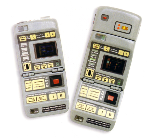
The standard tricorder measures 8.5 x 12 x 3 cm and masses 353 grams. The case is constructed of micromilled duranium foam, and is divided into two hinged sections for compact storage. The control surfaces consist of ruggedized positive-feedback buttons and a 2.4 x 3.6 cm display screen. While a full personal access display device-type multilayer control screen would have afforded the user with a wider range of preferences in organizing commands and visual information, the simplified button arrangement was chosen for greater ease of use in the field. The internal electronics, on the other hand, were designed to provide the greatest number of possible options in managing sensor data, visual images, and multichannel communications, in all incoming, outgoing, or recorded modes.
The major electronic components include the primary power loop, sensor assemblies, parallel processing block, control and display interface, subspace communication unit, and multiple memory storage units.
Power is provided to the total system through a rechargeable sarium crystal rated for eighteen hours of full instrument activity. True power usage rate and maximum useful time is, of course, dependent on which subsystems are active, and is continuously computed for call-up on the display. Typical power usage is 15.48 watts. The sensor assemblies incorporate a total of 235 mechanical, electromagnetic, and subspace devices mounted about the internal frame as well as imbedded in the casing material as conformal instruments. One hundred and fifteen of these are clustered in the forward end for directional readings, with a field-of-view (FOV) lower limit of 1/4 degree. The other 120 are omnidirectional devices, taking measurements of the surrounding space. The deployable hand sensor incorporates seventeen high-resolution devices for detailed readings down to an FOV of one minute of arc. Within these FOV limits, both active and passive scans can provide readings approaching the theoretical limits of the EM radiation of physical process under study. By combining readings from different sensors, the tricorder computer processors can synthesize images and numerical readouts to be acted upon by the crew member.
The computer capabilities of the standard tricorder are distributed throughout the device as preprocessors attached to the various sensors and twenty-seven polled main computing segments (PMCS). Each PMCS contains subsections dedicated to rapid management of the sensor assemblies, prioritizing of processing tasks, routing of processed data, and management of control and power systems. The PMCS chips supplied with the TR-580 and TR-595H(P) standard tricorders are rated at 150 GFP calculations per second.
The control and display interface (CDI) routes commands from both the panel buttons and display screen to the PMCS for execution of tricorder functions. Multiple functions can be run simultaneously, limited only by PMCS speed. In practice, crew members usually carry out no more than six separate scanning tasks.
Communications functions are carried out by tricorder through the subspace transceiver assembly (STA). Voice and data are uplink/downlinked along standard communicator frequencies. Transmission data rates are variable, with a maximum speed in Emergency Dump Mode of 825 TFP. Communication range is limited to 40,000 km intership, similar to the standard communicator badge.
The data storage sections of the standard tricorder include fourteen wafers of nickel carbonitrium crystal for 0.73 kiloquads of interim processor data storage, and three built-in isolinear optical chips, each with a capacity of 2.06 kiloquads, for a total of 6.91 kiloquads. The swappable library crystal chips are each formatted to hold 4.5 kiloquads. In Emergency Dump Mode, all memory devices are read in sequence and transmitted, including any library chips in place. In practice, the total time to dump a standard tricorder's memory to a starship/starbase can be as long as 0.875 seconds.
GENERAL DESCRIPTION OF CONTROLS AND INDICATORS
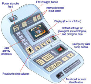
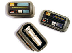
When stowed, the only visible control is the power switch. It shows a red power-on light and a green power level indicator. When deployed, all of the available controls are visible.
* PWR STBY - Power standby light. If the tricorder is not used for more than ten minutes, this indicator will illuminate, and the tricorder goes into low-power mode. Any new touch of any control will bring the device back up to full power. When the tricorder is stowed but performing ongoing tasks, low-power mode does not occur.
* F1/F2 - Control function select switch. Most buttons on the tricorder have more than one function. This is a convenient toggle for often-repeated function changes and may be preprogrammed by the individual crew member. The F1/F2 switch is active during data operations only.
* I and E - These two controls manage the source of sensory information, either the tricorder itself (Internal), or remote device (External), or both sources simultaneously. The remote device can be any sensor platform that uses the same data collection machine language. The term 'platform' denotes a vehicle operating on or above another planetary body, including the USS Enterprise or other spacecraft.
* DISPLAY SCREEN - This screen is capable of showing any realtime, stored, or computed image. The display area is similar in construction and function to Starfleet control panels and display screens, although the layering technique is simplified and the default image size is naturally smaller. Selected areas of an image may be enlarged by touch; many other screen functions may be customized using the standard tricorder's stored setup programs.
* LIBRARY A/B - The standard tricorder contains a read/write drive to record information onto small crystal memory chips for later retrieval, or to load previously recorded information into the tricorder's main memory. Each chip has a maximum capacity of 4.5 kiloquads.
* ALPHA BETA DELTA GAMMA - These indicators denote which data recording or retrieval activity is taking place in the tricorder library section. A more detailed readout of data operations can be called up on the display screen.
* DEVICE INPUT - Each of these three keys can be assigned to manage up to nine remote devices, for a total of twenty-seven different information sources. For a routine away mission, the default settings on power-up are GEO, MET, and BIO, covering geological, meteorological, and biological functions.
* COMM TRANSMISSION - This section controls the transmission of data and images to and from the tricorder through the STA. ACCEPT toggles the tricorder to accept one-way transmissions from a designated remote source. POOL allows for networking of the tricorder and one or more designated remote sources. INTERSHIP sets up a special tricorder-to-ship data link employing multiple high-capacity channels. TRICORDER sets up a similar high-capacity link, but to other tricorders. While all four modes can be active simultaneously, the system will slow down significantly. In practice, no more than two modes are usually necessary at one time.
* EMRG - This is the emergency 'dump everything to the ship' button. It provides for non-error-checking burst mode data transmission in critical situations. In practice, this function can be used no more than two times before the standard tricorder's primary power is exhausted. All sensing tasks are suspended and power is maximized to the STA.
* IMAGE RECORD - This section manages single or sequential image files recorded by the standard tricorder. The control has four divisions: FORWARD, REVERSE, INPUT, and ERASE. When used in concert with other tricorder functions, relatively complete documentation of an away mission can be achieved. At standard imaging resolution, at a normal recording speed of 120 Area View Changes (AVC)/sec, the tricorder can store a total of 4.5 hours of sequential images. Higher speeds yield a proportionately lower total recording time.
* LIBRARY B - Library B is the primary storage area for sequential images, though the memory configuration may be changed to include other storage areas, depending on the application. I and E control the image source.
* ID - This touchpad may be used to personalize a tricorder for default power-up settings, or as a security device for single-crew member operation.